My shopping cart
Your cart is currently empty.
Continue Shopping4727 N Damen Ave Chicago, IL 60625 | 773.878.8616 | rocknrollvintage@gmail.com | Showroom Hours: 12-6pm Tuesday-Friday | Saturday 12-5pm (Closed: Sunday/Monday)
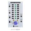
STG Soundlabs Trigger Sequencer


The trigger sequencer is a microprocessor-controlled sixteen-stage trigger sequencer. stage status (on/off) is controlled by a slide switch, and current stage indication is provided by eight green leds and two yellow leds in a row/column configuration. stages one through eight are on the left column, and stages two through sixteen are in the right column. The real power of this module, like the graphic sequencer, is that multiple units can be linked internally to the time buffer module which allows them all to be controlled (rate and restart) from a master sequencer or drum machine via the "din sync" connection. Controls: Stages - these slide switches control wether the stage sends a trigger or not. the duty cycle of the stage is 50 percent when advanced by the clock bus or the duty cycle of the incoming clock applied to the shift input. Length - this rotary switch controls how long the sequence is from two to sixteen stages. when a change is made at this control, it does not become active until the next cycle, which is very useful in a live context to allow more dynamic planning. Divisions switch - this switch is only active when the unit is connected to master sync via the time buffer. it allows you to select between quarter, eighth, and sixteenth-note rate for the sequencer. any time the rate is changed, the change will not take effect until the unit returns to stage one. this allows you to better keep track of where the sequencer will land in a live performance context. Stop/loop at end switch - this controls wether the sequencer stops at the last stage set by the length control or wether it returns to stage one and continues to advance from there. this could be used to either end phrases at certain times or use the sequencer as a burst generator for either rhythmic effects or handclaps. Connections: Shift input - gate signals presented at this input advance the stages forward incrementally. a 3.5 mm ts plug connected here tells the internal computer to stop advancing according to the internal sync bus and instead wait for pulses to appear at this connection. Stage one input - gate signals presented at this input return the sequencer to stage one for the duration of the input duty cycle. after the input returns to zero volts, the sequencer will wait for either the next logical clock from the sync bus or the next pulse presented to the shift input. Stage one output - this output presents a 5v pulse when the sequencer is returned to stage one whose duty cycle is either 1/32nd note in sync bus mode or the duration of the duty cycle of the gate signal driving the sequencer from the shift input. Output - here is where all of the sequential voltages spew forth from zero to five volts depending on what the sliders are set to. Power: this module, along with the time buffer and the graphic sequencer, uses only the five volt power rail of your system. if you do not have five volt power already in your system, a regulator board can be purchased which is strong enough to power 8 of these modules. it also has both doepfer and synthesizers.com power connectors to accommodate a variety of power situations.